
EN


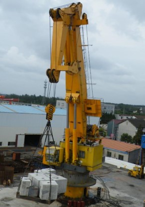
Knuckle boom marine crane
The knuckle boom marine crane/offshore crane is designed as an electro-hydraulic driven articulated boom crane, with integrated electro-hydraulic power package or independent electro-hydraulic power package, delivered as a complete unit ready for installation to foundation. The crane is equipped with hydraulic powered winch, hydraulic powered luffing, hydraulic powered articulated and hydraulic powered slewing system.
The Components of the crane
The hoisting winch is designed for operating in a marine environment.
It consists of gearbox with brake, hydraulic motor, and drum, etc. The
gearbox and brake system is built into the drum. The guard plates
are supplied for preventing wire rope escaping from drum.
The slewing bear is single row four point contacting ball type mounted on machined surface and designed for marine application. Fasteners for slewing ring are high-grade tension bolts ensuring the working condition for the bearing. The pinion drive is internally to protect the gearing from the marine environment. The slewing gearbox, brake, hydraulic motor are flanged together in one unit. The slewing bearing is equipped with suitable grease nipples.
3 Hydraulic Cylinders
The luffing cylinder is design for
Operation in a marine environment.
The piston rod is made of high tensile
chromed coated. Both ends of the
cylinder are equipped with self-lubricated
bearings. The cylinder has grease nipple for
greasing of the bearings.
Electric motor is mounted inside of the gantry with flexible
coupling drive to the pump. The oil tank is built in to the
gantry. The tank is equipped with full flow return filters,
Pressure gauge, air breathe ,The hole of air breathe can
be used for oil filling.
External hydraulic piping shall be of galvanized seamless carbon steel. Hydraulic hoses are selected for operation in a marine environment. All hoses are designed according class requirements for working pressure.
The crane is designed that one motion (hoisting, luffing, slewing) shall be made possible under the full capacity and full speed. And two motions shall be made possible simultaneously under the reduced capacity and reduced speed.
All movements are driven by hydraulic oil. All movements have stepless speed control from 0 to max.
When actual pressure is higher than the setting value, the relief valve will be opened. Winch motor, hydraulic cylinder and slewing motor are all provided with load holding valves which will freeze the movement in case of hose rupture or other failure causing pressure drop.
Emergency operated unit with manual pump, necessary valves, and the pipe line connected the unit with original system hydraulic motor including fitting.
The pressure of hydraulic system: ≤250Bar.
7.1 Electric source
Electric source from ship to crane is transmitted as follows:
Main power circuit :AC380V; 50Hz; 3P
7.2 Electric motor
The electric motor is of marine type. (IP56; Class of insulation “F”)
Motor will be provided with anti-condensation heater.
“Star-delta” type starter
Motor with cable gland
Motor in compliance with IEC requirement
7.3 Transformer for control voltage AC24V.
7.4 Start/Stop buttons in panel door.
7.5 Electric start box is IP56. It will be mounted on pedestal of crane by manufacturer.
The following safety limit devices are provided for the motions listed below. When the safety limit devices are actuated, the hydraulic and/or electric motor is stopped.
8.1 Hydraulic safety valves: Each safety valve protects the pumps as well as hoisting, luffing and slewing motors from over load.。
8.2 Hoisting limit
8.3 Emergency stop button: Motor stop running by pushing the button. The crane has 2 emergency stop buttons. One is on electric start box, another is on operation panel.
8.4 Emergency unloading valve: All motions are stopped when open the valve. It is mounted on operation platform.
8.5 Emergency relief system for hook
9 Surface treatment
The standard surface treatment procedure for cranes will be:
All surfaces Shot blasted to SA 2,5
One layer of epoxy zinc-rich primer - 50 microns
One layer of two pack epoxy - 100 microns
One layer of polyurethane - 70 microns
Total Dry film thickness - 220 microns
Related Products


CONTACT US
Contact US
Product Information
Quantity
Unit
Piece
Support order samples, customization, wholesale direct, and complete payment. If the product you look for does not have corresponding customized content, pls fill out the form below to contact us, and we will reply ASAP.